Tesla Tab Talk
Bosch Research Blog | Post by Jake Christensen, 2022-05-20


As a leading MEMS and sensor manufacturer, Bosch knows well that good things come in small packages. But in the case of batteries, which Bosch produces for electrified vehicles, power tools, and countless other products, bigger is actually better: increasing cell size makes them more economical.
Even Tesla Motors, which started an Electric Vehicles Renaissance with small commodity laptop cells, is going big. Earlier this month, Tesla debuted its much anticipated production 4680 cells (8x the size of a laptop cell) at the Giga Texas Cyber Rodeo. The new cell design was first publicly discussed at Tesla’s 2020 “Battery Day,” where CEO Elon Musk and Sr. VP of Powertrain and Energy Engineering Drew Baglino laid out a bold vision for dramatically increasing battery production, lowering cost, and increasing EV driving range. Along with a few audacious but vaguely described materials innovations, the Tesla duo provided more explicit details on a larger cylindrical cell design that would afford a 16% increase in range compared to batteries built from the 2170 (21 mm diameter, 70 mm length) cell design used in its other current production models. By virtue of its larger dimensions (46 mm dia., 80 mm length), the 4680 cell format has roughly 5 times the energy of a 2170, but all materials being equal, perhaps only a slight increase in energy density due to a smaller volume fraction of packaging material. The basis of the 16% range increase was not disclosed, but likely involves a combination of cell, pack, and vehicle packaging factor improvements.
It’s long been known that making bigger (especially longer) cells can lower the cost of cell manufacturing (in $/kWh), but the industry has not moved especially quickly in this direction, particularly with the cylindrical cell format. The key to enabling such a large design, according to Tesla, is a new innovation in “tabless” cell design,i which would improve power density, decrease charging times, improve thermal management, and simplify cell manufacturing to boot.
Let’s break down this claim one piece at a time. The “tabless” Tesla cell design is really a multi-tab design, or “shingled spiral” of tabs that have been “laser patterned.” The imagei shared with the public suggests a continuous tab (i.e., wherein an uncoated region of the current collector extends along the entire length of the unwound jellyroll) that is cut every 4 mm or so, with each segment of current collector folded over to form a composite metal disk. Okay, but what does this fancy design do for cell performance? As Musk and Baglino point out, such multi-tab or “continuous tab” architectures significantly reduce the electrical path length from terminals to active electrode materials compared to a more conventional single-tab design (i.e., with one tab welded to one end of the cathode current collector and another welded to one end of the anode current collector). Incredibly, these compact cylindrical cells contain rolled-up electrodes that, when unwound, are on the order of 1 m in length! Even the original 1865 cell used in the Tesla roadster (and most laptops since the early 90s), with a volume of ~17 mm, can have an electrode length of half a meter or more! That’s because the electrodes themselves, at ~50 to 100 microns, are only about as thick as a human hair. So, by moving from a single- to multi- or continuous tab design, we can cut the total electrical path length from ~3.5 mii to ~75 mm (almost 50x) in a 4680 cell.iii
Reducing the electrical path length compared to single-tab designs naturally lowers the resistance of the cell, resulting in less heating during charge and discharge. Hence, one can make a larger cell with slightly higher energy density due to a larger jellyroll/cell volume ratio (hence, lower cost/kWh). Moreover, for a given cell size, it’s possible to use thinner current collectors, further increasing the volume fraction of active materials and overall cell energy density.
The idea of including multiple tabs or a continuous tab is not new. It’s just very difficult to manufacture in a cylindrical design. Some successful and failed examples:
- Energizer has had cylindrically wound, continuous-tab primary lithium cells on the market for decades.iv However, these are not rated for high power as in a rechargeable Li-ion battery.
- In the early 2000s, A123 developed a concept for winding a metallic “guidewire” into a jellyroll with continuous tabs and then laser welding the structure together into a solid cap.v However, as far as the author is aware, this approach was never realized in mass production (A123 and the IP have since been sold).
There are, on the other hand, high-power prismatically wound cells on the market with continuous tabs that have more than double the capacity of the Tesla 4680 without a significantly greater electrical path length. Due to the prismatic format, continuous tabs are easily welded or clamped together and then connected to the cell terminals via a <10 cm secondary tab.vi
So, what impact does a reduced electrical path length actually have on cell performance? Tesla claims higher power density and decreased charging times. Some years ago, we at Bosch Research were interested in quantifying this impact and set about modeling and simulating the pertinent physics in an 1865 cell.
It turns out that, due to a wide range in length scales (microns to meters) over which electronic and ionic transport occur in a battery cell, it’s not tractable to model and compute all the relevant physics as a set of equations in 3D. Hence, we broke the cell physics into separable domains and scales, with a few coupling variables transmitted back and forth between the submodels on each timestep. Using clever mesh mapping and numerics,vii we succeeded in achieving convergence and saving a significant amount of computational expense. Computations can be sped up even further using a high-performance computing cluster, as many elements of the code are parallelizable.
Some of the more interesting observations derived from the 1865 simulations include:
- The current collectors contribute an impedance that appears to be ohmic (overpotential proportional to current), yet can have a pronounced impact on the state-of-charge distribution throughout the cell (see Figure 1).
- Similarly, there is some 3D variation in Li plating driving forces during fast charging. Hence, lowering the electrical resistance can help avoid plating.
- For a given cell sandwich geometry (electrode and current collector thickness), current collectors tend to have a more significant impact on the resistance of cells as the electrochemical resistance is decreased (see Figure 2).
-
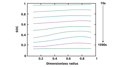
Figure 1. Variation of the state of charge (SOC) of the cell during discharge. Different colors represent evenly spaced time intervals during the cell discharge. The dimensionless radius is defined as r* = (r – r0) / (r1 – r0), where r0 is the inner radius of the jellyroll (at the mandrel) and r1 is the outer radius (adjacet to cell mantle). -
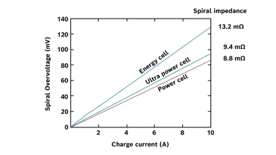
Figure 2. Simulated CC (“spiral”) overpotential and fitted impedance for several 1865s: “Energy cell:” high energy-to-power ratio, thick electrodes, thin current collectors; “Power cell:” high power-to-energy ratio, thin electrodes, thick current collectors; and “ultra Power cell:” hypothetical cell with the power cell geometry and enhanced electrochemical properties. The overpotential was calculated after 0.5Ah of simulated charging.
Keep in mind that these quantitative differences would be even more pronounced in a larger (e.g., 4680) format cell. So, does the multi-tab design improve power density? Yes — we computed a ~10% improvement even in 1865 designs. Does it enable higher charging rates? There is a notable difference in the maximum driving force for Li plating (i.e., plating can happen earlier and/or at lower charging rates in a single-tab cell than multi-tab cell due to current and SOC nonuniformity), but the most significant impact is likely in the rate of heat generation, especially for larger cells. Higher heat generation results in higher temperature, which during charging can mean faster parasitic reactions that degrade the cell’s performance and capacity.
Interestingly, Tesla claims that their architecture “removes the thermal problem from the equation.” Certainly, the heating due to electrical resistance of the current collectors is significantly reduced, but most of the heat generation comes from the electrochemistry itself, and a larger cell will generally be slower in rejecting that heat. Is Tesla then implying that the new design is more efficient at removing even the electrochemically generated heat? This hypothesis requires some scrutiny, as the current collector thickness as well as the cell size are the most important factors governing heat transfer rates. The Biot number (hL/k),ix or ratio of external convection into the cooling medium to the internal conduction of heat, determines the maximum temperature inside the cell for a given internal rate of heat generation. Thinner current collectors mean lower thermal conductivity (k), while larger cells mean higher heat conduction path length (L), both of which result in higher Biot numbers and higher, less uniform internal temperatures.
Let’s assume that the Tesla 4860 cell uses similar current collector thickness to the 2170 cell (i.e., to maintain similar jellyroll energy density). Even in this case, the much larger diameter of the 4860 cell will result in higher thermal resistance in the radial direction and therefore higher temperatures at a given rate of heat generation. There are likely some advantages to directly connecting the terminals to the “tabless” jellyroll at the top and bottom of the can, but it’s not clear that this would compensate for the higher radial thermal resistance, given that the thermal conductivity along current collectors is typically an order of magnitude higher than the thermal conductivity perpendicular to the current collectors.x Again, the principal thermal advantage of the multi-tab architecture is related to reduced rates of heat generation, not the heat transfer characteristics.
The interplay between thermal and electrochemical phenomena in batteries is both fascinating and critical to the design of batteries. We applied the same general “multiscale, cross-domain” approach used for electrical-electrochemical coupling in order to quantify temperature distribution and current/aging nonuniformity in cells due to thermal effects, where electrochemistry generates heat and electrochemical properties depend on temperature.xi An added benefit is that we can parallelize the code and compute performance of large-format cells and even battery packs on a high-performance computing cluster in a reasonable amount of time (e.g., 30 min for a discharge curve on 8 cores).
In recent and forthcoming joint publications with Stanford University,xii we have extended this framework to include mechanics to understand how active material volume changes and applied pressure result in nonuniform mechanical deformation and Li plating behavior.
Presently we are applying the same multiscale, cross-domain approach to the simulation of PEM fuel cells, where the electrochemistry interacts with complex fluid flow and conjugate heat transfer.
Design of electrochemical systems and optimizing their operation for high performance/cost ratio and durability requires complex models to address complex and highly coupled physical phenomena. By separating domains and scales and linking them in the right way, we can make these problems tractable and accelerate our understanding and optimization of these devices.
Most battery and fuel cell companies have used trial and error, which is expensive and slow. If we want to do better, we have to apply the right tools. Commercial modeling software often fails to capture the full complexity required for meaningful battery simulations, does not handle multiple scales efficiently, or scales poorly on high-performance computers. Electrochemical device optimization typically requires custom SW solutions and can be well worth the investment.
We don’t know whether Tesla relied on similar models to ultimately arrive at the new multi-tab 4680 cell or what the rate-limiting step was in getting there. Working out a manufacturable solution is no small feat, and there remain a few mysterious ingredients in their “secret sauce” (how, for instance, is electrolyte introduced into the cell — does this happen before the tabs are folded over?). But certainly physics-based, computationally efficient models can be an invaluable tool in optimizing product design while eliminating expensive and time-consuming trial-and-error prototyping. By applying virtual design to electric powertrains and many other products aimed at lowering emissions, especially CO₂. We should now invest in faster approaches to tackle climate change.
What are your thoughts on this topic?
Please feel free to share them or to contact me directly.

Jake Christensen
Jake directs the Energy Systems and Materials Modeling department at the Research and Technology Center in North America and is the Chief Battery Modeling Engineer. His team develops electrochemical devices for reliable, affordable electromobility and clean, efficient use of our natural resources. They elucidate complex phenomena through modeling and simulation from the atom to system scale, fundamental material property measurement, and operando characterization.
Sources
ii assuming 80% volume packaging factor and 400-um thickness including double-sided electrodes and two separator layers in the jellyroll.
iii Tesla cites 5x decrease in path length from single-tab 2170 to tables 4680.
iv https://data.energizer.com/PDFs/lithiuml91l92_appman.pdf, https://patentimages.storage.googleapis.com/49/3d/18/3633b1de87e0ec/US8617259.pdf, https://patentimages.storage.googleapis.com/c0/f0/99/0c5cfdbef02597/US5188909.pdf, https://www.energizer.com/about-batteries/battery-history
v https://patentimages.storage.googleapis.com/04/9e/ca/e4f6625b5530ba/US20050277019A1.pdf
vi https://www.yuasa.co.uk/info/industrial-applications/introduction-to-lithium-ion-batteries/, http://www.optimumnanolithiumbattery.com/news/analysis-of-samsung-sdi-power-battery-technolo-4920947.html
vii Christensen, Patnaik, Albertus, and Cook, ECS Meeting Abstracts (2011), https://iopscience.iop.org/article/10.1149/MA2011-02/15/749/meta; S. Patnaik, An electrical network model for computing current distribution in a spirally wound lithium ion cell, MS Thesis, Department of Electrical Engineering and Computer Science, Massachusetts Institute of Technology: Cambridge, MA (2012), https://dspace.mit.edu/handle/1721.1/85400; Christensen et al., J. Electrochem. Soc. (2022), https://doi.org/10.1149/1945-7111/ac71d3
ix h = heat transfer coefficient (W/m2-K); k = thermal conductivity (W/m-K); L = length or radius (m)
x H. Maleki, S. Al Hallaj, J. R. Selman, R. B. Dinwiddie, and H. Wang, J. Electrochem. Soc. (1999), https://doi.org/10.1149/1.1391704
xi Christensen, Cook, and Albertus, J. Electrochem. Soc. (2013), https://doi.org/10.1149/2.086311jes; Kim et al., J. Power Sources (2014), https://doi.org/10.1016/j.jpowsour.2014.06.080
xii Zhang et al., J. Electrochem. Soc. (2020), https://doi.org/10.1149/1945-7111/abd1f2; Zhang et al., J. Electrochem. Soc. (2021), https://doi.org/10.1149/1945-7111/abe16d; Qiu et al., J. of Power Sources (2022), https://doi.org/10.1016/j.jpowsour.2022.231632